Difference between revisions of "BGRABitmap tutorial 10"
Jwdietrich (talk | contribs) |
m (Fixed syntax highlighting) |
||
| Line 11: | Line 11: | ||
=== Using no particular mapping === | === Using no particular mapping === | ||
| − | Let's see what happens if we draw a polygon with a texture using default mapping : | + | Let's see what happens if we draw a polygon with a texture using default mapping: |
| − | <syntaxhighlight>procedure TForm1.FormPaint(Sender: TObject); | + | |
| + | <syntaxhighlight lang="pascal"> | ||
| + | procedure TForm1.FormPaint(Sender: TObject); | ||
var image: TBGRABitmap; | var image: TBGRABitmap; | ||
tex: TBGRABitmap; | tex: TBGRABitmap; | ||
| Line 25: | Line 27: | ||
image.Draw(Canvas,0,0,True); //draw on the screen | image.Draw(Canvas,0,0,True); //draw on the screen | ||
image.free; | image.free; | ||
| − | end; </syntaxhighlight> | + | end; |
| + | </syntaxhighlight> | ||
=== Run the program === | === Run the program === | ||
| − | You should obtain something like this : | + | You should obtain something like this: |
[[Image:BGRATutorial10a.png]] | [[Image:BGRATutorial10a.png]] | ||
| Line 37: | Line 40: | ||
=== Affine transformation === | === Affine transformation === | ||
| − | We can apply an affine transformation like this : | + | We can apply an affine transformation like this: |
| − | <syntaxhighlight>uses BGRABitmap, BGRABitmapTypes, BGRATransform; | + | |
| + | <syntaxhighlight lang="pascal"> | ||
| + | uses BGRABitmap, BGRABitmapTypes, BGRATransform; | ||
procedure TForm1.PaintImage; | procedure TForm1.PaintImage; | ||
| Line 63: | Line 68: | ||
image.Draw(Canvas,0,0,True); //draw on the screen | image.Draw(Canvas,0,0,True); //draw on the screen | ||
image.free; | image.free; | ||
| − | end;</syntaxhighlight> | + | end; |
| + | </syntaxhighlight> | ||
=== Run the program === | === Run the program === | ||
| − | You should obtain a rotated picture in the polygon : | + | You should obtain a rotated picture in the polygon: |
[[Image:BGRATutorial10b.png]] | [[Image:BGRATutorial10b.png]] | ||
| Line 77: | Line 83: | ||
==== Linear mapping ==== | ==== Linear mapping ==== | ||
| − | Linear mapping stretched the image linearly along the borders. To do this : | + | Linear mapping stretched the image linearly along the borders. To do this: |
| − | <syntaxhighlight>procedure TForm1.PaintImage; | + | |
| + | <syntaxhighlight lang="pascal"> | ||
| + | procedure TForm1.PaintImage; | ||
var image: TBGRABitmap; | var image: TBGRABitmap; | ||
tex: TBGRABitmap; | tex: TBGRABitmap; | ||
| Line 91: | Line 99: | ||
image.Draw(Canvas,0,0,True); | image.Draw(Canvas,0,0,True); | ||
image.free; | image.free; | ||
| − | end; </syntaxhighlight> | + | end; |
| + | </syntaxhighlight> | ||
To do the mapping, we use FillPolyLinearMapping. Some new parameters appear. Texture coordinates define, for each point of the polygon, the location in the texture. Interpolation option is used for best quality. | To do the mapping, we use FillPolyLinearMapping. Some new parameters appear. Texture coordinates define, for each point of the polygon, the location in the texture. Interpolation option is used for best quality. | ||
| Line 104: | Line 113: | ||
The perspective mapping allow to change the depth of each point. | The perspective mapping allow to change the depth of each point. | ||
| − | <syntaxhighlight>procedure TForm1.PaintImage; | + | |
| + | <syntaxhighlight lang="pascal"> | ||
| + | procedure TForm1.PaintImage; | ||
var image: TBGRABitmap; | var image: TBGRABitmap; | ||
tex: TBGRABitmap; | tex: TBGRABitmap; | ||
| Line 124: | Line 135: | ||
==== Run the program ==== | ==== Run the program ==== | ||
| − | Now it seems that it is a 3D polygon : | + | Now it seems that it is a 3D polygon: |
[[Image:BGRATutorial10d.png]] | [[Image:BGRATutorial10d.png]] | ||
Revision as of 14:01, 3 January 2020
│ Deutsch (de) │ English (en) │ español (es) │ français (fr) │
Home | Tutorial 1 | Tutorial 2 | Tutorial 3 | Tutorial 4 | Tutorial 5 | Tutorial 6 | Tutorial 7 | Tutorial 8 | Tutorial 9 | Tutorial 10 | Tutorial 11 | Tutorial 12 | Tutorial 13 | Tutorial 14 | Tutorial 15 | Tutorial 16 | Edit
This tutorial shows how to use texture mapping.
Create a new project
Create a new project and add a reference to BGRABitmap, the same way as in the first tutorial.
Using no particular mapping
Let's see what happens if we draw a polygon with a texture using default mapping:
procedure TForm1.FormPaint(Sender: TObject);
var image: TBGRABitmap;
    tex: TBGRABitmap;
begin
  //black background
  image := TBGRABitmap.Create(ClientWidth,ClientHeight, BGRABlack );

  tex:= TBGRABitmap.Create('image.png'); //load a bitmap
  image.FillPolyAntialias( [PointF(110,10), PointF(250,10), PointF(350,160), PointF(10,160)], tex);
  tex.Free;

  image.Draw(Canvas,0,0,True); //draw on the screen
  image.free;
end;
Run the program
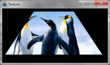
You should obtain something like this:
As you can see the image is not deformed.
Affine transformation
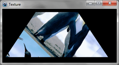
We can apply an affine transformation like this:
uses BGRABitmap, BGRABitmapTypes, BGRATransform;

procedure TForm1.PaintImage;
var image: TBGRABitmap;
    tex: TBGRABitmap;
    affine: TBGRAAffineBitmapTransform;

begin
  //black background
  image := TBGRABitmap.Create(ClientWidth,ClientHeight, BGRABlack );

  tex:= TBGRABitmap.Create('image.png'); //load a bitmap

  //create a rotation of 45°
  affine := TBGRAAffineBitmapTransform.Create(tex,True);
  affine.RotateDeg(45);

  //use this transformation as parameter instead of tex
  image.FillPolyAntialias( [PointF(110,10), PointF(250,10), PointF(350,160), PointF(10,160)], affine);

  affine.Free;
  tex.Free;

  image.Draw(Canvas,0,0,True); //draw on the screen
  image.free;
end;
Run the program
You should obtain a rotated picture in the polygon:
Texture mapping
Now, if we want the texture to be aligned with the polygon border, we can use texture mapping.
Linear mapping
Linear mapping stretched the image linearly along the borders. To do this:
procedure TForm1.PaintImage;
var image: TBGRABitmap;
    tex: TBGRABitmap;
begin
  image := TBGRABitmap.Create(ClientWidth,ClientHeight, BGRABlack );

  tex:= TBGRABitmap.Create('image.png');
  image.FillPolyLinearMapping( [PointF(110,10), PointF(250,10), PointF(350,160), PointF(10,160)], tex,
             [PointF(0,0), PointF(tex.width-1,0), PointF(tex.Width-1,tex.Height-1), PointF(0,tex.Height-1)], true);
  tex.Free;

  image.Draw(Canvas,0,0,True);
  image.free;
end;
To do the mapping, we use FillPolyLinearMapping. Some new parameters appear. Texture coordinates define, for each point of the polygon, the location in the texture. Interpolation option is used for best quality.
Run the program
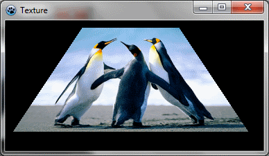
Now the texture is deformed according to the polygonal shape.
Perspective mapping
The perspective mapping allow to change the depth of each point.
procedure TForm1.PaintImage;
var image: TBGRABitmap;
    tex: TBGRABitmap;
begin
  image := TBGRABitmap.Create(ClientWidth,ClientHeight, BGRABlack );

  tex:= TBGRABitmap.Create('image.png');
  image.FillPolyPerspectiveMapping( [PointF(110,10), PointF(250,10), PointF(350,160), PointF(10,160)],
                                    [75,             75,             50,              50],
       tex, [PointF(0,0), PointF(tex.width-1,0), PointF(tex.Width-1,tex.Height-1), PointF(0,tex.Height-1)], true);
  tex.Free;

  image.Draw(Canvas,0,0,True);
  image.free;
end;
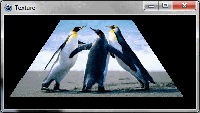
Here the depth is 75 for the top of the polygon and 50 for the bottom of the polygon. It means that the bottom is closer to the observer, as if it were horizontal, like a floor.
Run the program
Now it seems that it is a 3D polygon:
Conclusion
Using these techniques, it is possible to deform an image, like in LazPaint tool "grid deformation", or to render 3D objects with textures, like in tests 19-21 of testbgrafunc (also in LazPaint archive).
Previous tutorial (phong shading) Next tutorial (combining transformations)


