Difference between revisions of "BGRABitmap tutorial 15"
(created) |
|||
| Line 47: | Line 47: | ||
An object has a Vertices property which allows to create and access to vertices. Coordinates can be given as three single values, TPoint3D records, or an array of single values which length must be a multiple of 3. When you create a vertex, you receive an IBGRAVertex interface which can be used to create faces. | An object has a Vertices property which allows to create and access to vertices. Coordinates can be given as three single values, TPoint3D records, or an array of single values which length must be a multiple of 3. When you create a vertex, you receive an IBGRAVertex interface which can be used to create faces. | ||
| + | |||
| + | The X axis points to the right, the Y axis points to bottom, and the Z axis points forward (behind the screen). It means that XY works the same way as in a bitmap, and there is a depth value. The faces must be in clockwise order to be visible. | ||
Here the color is set for the whole object when creating it, but you can set it individually for each face, or for each vertex. | Here the color is set for the whole object when creating it, but you can set it individually for each face, or for each vertex. | ||
| Line 53: | Line 55: | ||
As you can see, the pyramid is view from one side, so we can only see one face. There is no lighting either. | As you can see, the pyramid is view from one side, so we can only see one face. There is no lighting either. | ||
| + | |||
| + | In the 'with' block, add the following lines : | ||
| + | <delphi> Vertices.Scale(1.3); | ||
| + | Vertices.RotateYDeg(30); | ||
| + | Vertices.RotateXDeg(20); | ||
| + | Vertices.Translate(0,-5,0); </delphi> | ||
| + | The first line makes the object a little bigger. The two rotations are applied. The first is around the Y axis and the second around the X axis. To figure out the rotation sign, imagine you look in the direction of the axis. A positive value in degree means a clockwise rotation, and a positive value in radian means an anti-clockwise rotation. | ||
| + | |||
| + | Finally a vertical translation is applied to center the object. | ||
| + | |||
| + | [[Image:BGRATutorial15b.png]] | ||
| + | |||
| + | Now let's add some lighting : | ||
| + | <delphi> //set ambiant lightness to dark (1 is normal lightness, 2 is complete whiteness) | ||
| + | scene.AmbiantLightness := 0.5; | ||
| + | //add a directional light from top-left, maximum lightness will be 0.5 + 1 = 1.5 | ||
| + | scene.AddDirectionalLight(Point3D(1,1,1), 1); </delphi> | ||
| + | |||
| + | The example uses lightness values. 0 means black, 1 means unchanged color, and 2 means white. The directional takes a Point3D parameter to indicate the direction of the ray. It does not need to be normalized. | ||
| + | |||
| + | [[Image:BGRATutorial15c.png]] | ||
[[BGRABitmap tutorial 14|Previous tutorial (canvas 2D)]] | [[BGRABitmap tutorial 14|Previous tutorial (canvas 2D)]] | ||
[[Category:Graphics]] | [[Category:Graphics]] | ||
Revision as of 18:10, 6 July 2011
│ Deutsch (de) │ English (en) │
Home | Tutorial 1 | Tutorial 2 | Tutorial 3 | Tutorial 4 | Tutorial 5 | Tutorial 6 | Tutorial 7 | Tutorial 8 | Tutorial 9 | Tutorial 10 | Tutorial 11 | Tutorial 12 | Tutorial 13 | Tutorial 14 | Tutorial 15 | Tutorial 16 | Edit
This tutorial shows how to render 3D objects using the TBGRAScene3D object.
Scene object
The scene object is in BGRAScene3D unit. Here is a simple example : <delphi> procedure TForm1.FormPaint(Sender: TObject); var
 scene: TBGRAScene3D;
 bmp: TBGRABitmap;
 base: array of IBGRAVertex3D;
 topV: IBGRAVertex3D;
begin
bmp := TBGRABitmap.Create(ClientWidth,ClientHeight,BGRABlack);
 scene := TBGRAScene3D.Create(bmp);
 //create a pyramid
 with scene.CreateObject(BGRA(255,240,128)) do
 begin
   //create vertices
   topV := Vertices.Add(0,-15,0);
   //pyramid base is in a clockwise order if we look the pyramid from under
   base := Vertices.Add([-20,15,-20, 20,15,-20, 20,15,20, -20,15,20]);
   AddFace(base);
   //add four faces, the three vertices are in a clockwise order
   AddFace([base[0],topV,base[1]]);
   AddFace([base[1],topV,base[2]]);
   AddFace([base[2],topV,base[3]]);
   AddFace([base[3],topV,base[0]]);
 end;
 scene.Render;
 scene.Free;
 bmp.Draw(Canvas,0,0);
 bmp.Free;
end; </delphi>
The scene object draws itself on a TBGRABitmap object. You can either pass the bitmap as a parameter when creating the object, as done here, or assign the Surface property afterwards. The scene is automatically centered in the bitmap.
The scene object provides CreateObject function, which returns an interface to the created object. Objects inside a scene are freed automatically when you free the scene.
An object has a Vertices property which allows to create and access to vertices. Coordinates can be given as three single values, TPoint3D records, or an array of single values which length must be a multiple of 3. When you create a vertex, you receive an IBGRAVertex interface which can be used to create faces.
The X axis points to the right, the Y axis points to bottom, and the Z axis points forward (behind the screen). It means that XY works the same way as in a bitmap, and there is a depth value. The faces must be in clockwise order to be visible.
Here the color is set for the whole object when creating it, but you can set it individually for each face, or for each vertex.
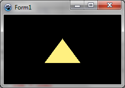
As you can see, the pyramid is view from one side, so we can only see one face. There is no lighting either.
In the 'with' block, add the following lines : <delphi> Vertices.Scale(1.3);
   Vertices.RotateYDeg(30);
   Vertices.RotateXDeg(20);
   Vertices.Translate(0,-5,0);  </delphi>
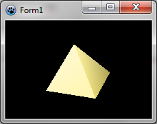
The first line makes the object a little bigger. The two rotations are applied. The first is around the Y axis and the second around the X axis. To figure out the rotation sign, imagine you look in the direction of the axis. A positive value in degree means a clockwise rotation, and a positive value in radian means an anti-clockwise rotation.
Finally a vertical translation is applied to center the object.
Now let's add some lighting : <delphi> //set ambiant lightness to dark (1 is normal lightness, 2 is complete whiteness)
 scene.AmbiantLightness := 0.5;
 //add a directional light from top-left, maximum lightness will be 0.5 + 1 = 1.5
 scene.AddDirectionalLight(Point3D(1,1,1), 1);   </delphi>
The example uses lightness values. 0 means black, 1 means unchanged color, and 2 means white. The directional takes a Point3D parameter to indicate the direction of the ray. It does not need to be normalized.


